From a DFB Gasifier the produced synthesis gas, which has high contents of hydrogen and carbon monoxide, is highly suitable for hydrogen production. High efficiencies of more than 60% can be reached by generating hydrogen from biomass and total efficiencies of up to 80% are possible by utilization of waste heat. Here, 320 kW of extrinsic energy are required for 1000 kWh of H2. By comparison, generating the same amount of H2 via electrolysis would need 3000 kWh of energy.
Hydrogen plant through above technology is most effective for production decentrally at low cost. This can be installed close to highways or traffic model centers, where biomass is available locally to avoid transportation of hydrogen. A fully distributed network can be designed at the places where trucks, buses and passenger cars are widely available.
Process
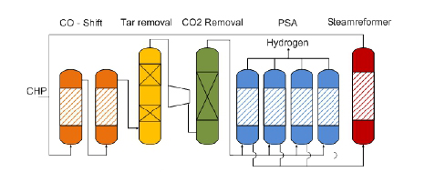
For hydrogen production, the syngas generated out of DFB Gasifier needs further processing. First, filter to remove dust particles, thereafter a water gas shift stage to enhance the hydrogen output, an organic scrubber to remove water and tar out of the syngas, a CO2 removal stage to separate sour gas components, a hydrogen purification unit to produce high quality hydrogen and finally, a tail gas reforming step to enhance the efficiency of the plant.
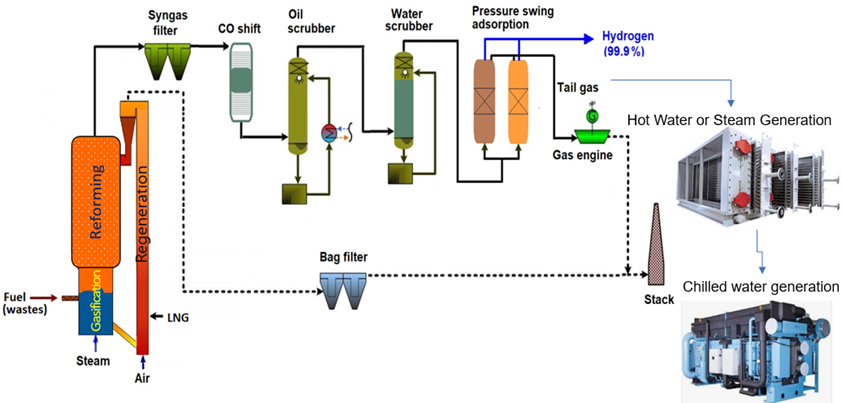
The main components of the GH2 plant are shown in the diagram below.
The tar-rich syngas from DFB gasifier is mixed with recycled gas from the steam reformer and sent over a two-staged water gas shift reactor (orange).
A high temperature sour gas shift catalyst, based on iron and chromium, is used for the water gas shift process. The carbon monoxide and steam in the gas are converted to carbon dioxide and hydrogen according to water gas shift equation :
CO + H20 <–> CO2 + H2
The CO shift process is operated at atmospheric pressure and temperature up to 4500 C at the outlet of the shift reactors.
After the gas has passed the water gas shift stage, it enters a two-stage organic scrubber (yellow), operated with rape seed methyl ester (RME). In this scrubber, tars are removed and water is condensed down to 3% moisture content in the syngas. The scrubber fluid has to be cooled to ensure the necessary separation efficiency.
Then, the gas is compressed and sour gas components (CO2, H2S) are removed by an amine scrubber (green) operated at a pressure of 23 bars. The temperature in the CO2 absorber is set at 400 C.
With a pressure swing adsorption (blue), the hydrogen of the gas is recovered by adsorption of impurities on a molecular sieve and activated carbon. This hydrogen has high purity and can be further used for energy generation.
The tail gas of the PSA, which has a high content of hydrocarbons, is splitted, the main part is sent in to a steam reformer (red) to covert the hydrocarbons in to carbon monoxide, carbon dioxide and hydrogen according to the general steam reforming equation :
CxHy + xH20 <–> ( x + y/2 ) H2 + CO
The reformed gas is sent back to the water gas shift stage to achieve a better efficiency. The other part of the tail gas is sent back to the combustion zone of the gasifier represent the amount of gas necessary for heating the reformer.
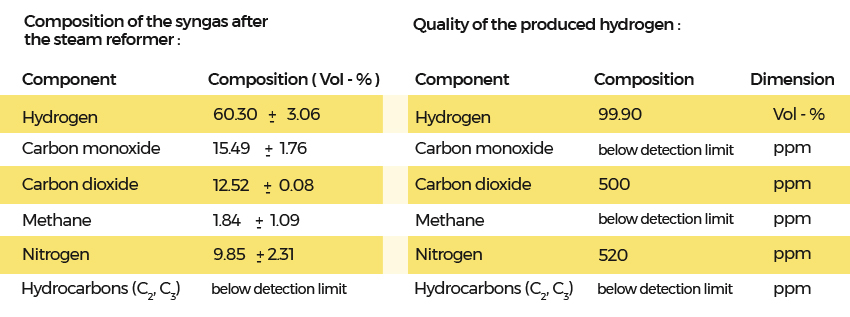
The impurities were caused by nitrogen, which was used for online cleaning of bag filters in the gasifier. These cleaning activities can be performed with the separated carbon dioxide. This would result in low nitrogen content in the producer gas.